I've got a couple WRT54Gx units running DD-WRT. I've got a few SD memory cards. I've got a nice soldering iron. I like to tinker with things. What better project than to add a MMC/SD memory card adapter to the WRT routers! All I need is some solder, some thin wire (old 28ga PC ribbon cable? Perfect!), an MMC/SD adapter and time to assemble.
Problem: I'm a cheap bastard. :D
I had started this with the directions for using an old card-edge floppy connecter available at Up All Night Robotics. (http://uanr.com/sdfloppy/) Excellent, it worked! Didn't cost me a cent as I had all the parts avaiable in my accumulated computer bits.
So I ran with it for a week or two, had the cable routed outside of the WRT shell so the card was accessible. I was pleased.
Until I realized how crappy it looked. (and with my floppy connector the card was a tight fit.)
The quest was on for something better. I knew I could pick up a MMC/SD breakout board at Spark Fun (www.sparkfun.com) as many had done before but $15 before shipping didn't appeal to my cheapskate side. I could get just the connector for $4 before shipping, but it didn't look like it had much mounting surface. I considered just soldering to a SD-to-mini(or micro)SD adapter, but then again mounting might be difficult and it would further limit my memory card options. It then dawned on me to do what I had done in many projects before. Find something that I could use parts from and tear the damn thing apart! What I opted for were the MMC/SD to USB card adapters that could escentially be used as a keystick. I've picked them up from Super Media Store (www.supermediastore.com), Meritline (www.meritline.com) or Go Go Cost (www.gogocost.com) for as little as $3 shipped. Just el cheapo adapters with just a few components to remove.
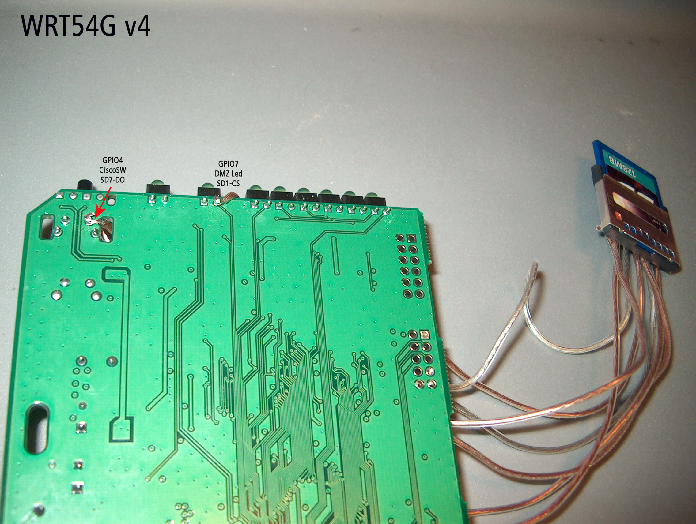
Actually, I probably didn't even need to remove the other components but I did anyway, just stripping the assembly down to the card socket and circuit board. If you do this just make sure to watch that you don't bridge any solder pads and if you lift any traces in the process that they get cut off the board so as not to short on anything. This left me with an enclosed socket and plenty of mounting area on the circuit board. The solder points on the back of the socket were tricky to get to, but if I first added a little solder to the point and made sure I had tinned the wire I would attach it was much easier. Follow directions available online for linking the 7 necessary socket pins to GPIO, power and ground points and voila! A cheap, working MMC/SD mod that works better and isn't quite so crappy looking. I completed this on a couple WRT54G devices.


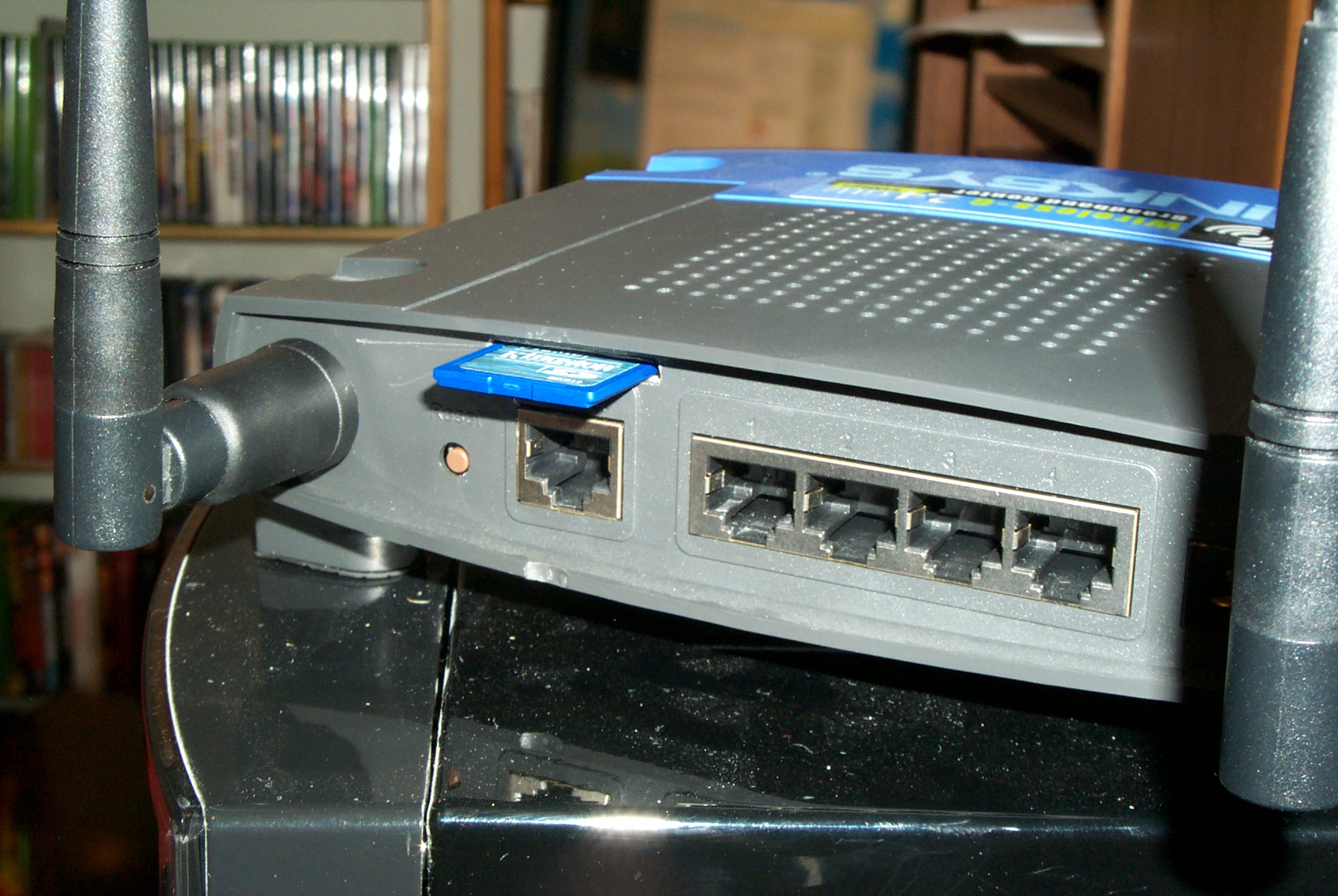
Now to really trick this out and make it look "factory." Goals here were to find a way to mount the card so that the slot looked in line with the design and to also fasten it in an orientation where the card pins were facing down. Ok, the second bit is a real a minor thing but I didn't want an inserted card to appear "upside down." This requirement ruled out mounting the card socket to the lid of the router since I didn't want to use the metal top of the card socket as a mounting surface. If I attempted to attach the socket to the blue front it would then create problems when taking the router apart as the front and the mainboard would now be teathered. I felt having the card out the side of the router didn't meet the design-flow requirement. Looking at the back panel I realized I could have the card slot above the RJ-45 ports and anchor the socket to the port shell. Since I was going to be using a hot glue gun to do the mounting the RJ-45 shells would be a good mounting point. The smooth surface should break clean from the glue if I need to remove the socket but the hot glue would still adhere enough for normal card swapping. I pulled out my Dremel tool with a cutting wheel and notched out a slot just above the raised area for the WAN port. I chose above the WAN port as opposed to above the switch ports as the WAN port if off by itself and the MMC/SD card will also be a single component. It may also be more important to easily see the port numbers for the switch, having the card over the WAN port doesn't obscure these numbers and the WAN port being separated out sort of indicates it's purpose.


It took a little bit of trickery to get this mounted the way I wanted with the hot glue. There are two ways to go about this to get the first anchor in place. One is to have a card in the socket and through the slot, then put the top half of the shell partially back on, at least over the antenna mounts but hinged open. Then hit the underside of the MMC/SD socket and the top of the WAN jack with enough hot glue to hold it at the correct height. Then close up the two shell pieces. Don't expect it to hold in the right position on it's own until the glue cools. You'll probably want to hold this upside down so that any glue that runs goes harmlessly on the bottom of the MMC/SD socket or the lid of the router. While this is cooling hold the bit of the card sticking outside of the shell in the desired mounting position. The other method is to put a blob of hot glue on the WAN jack, set the MMC/SD socket in the glue and then lift and hold it in about the right position. The column of glue that forms between the jack and the socket should remain flexible enough once it starts to set that you can tweak the alignment of the socket and the slot in the back of the shell. Once this first shot of glue from either method has set in the desired position go back and beef up the mount with a bit more. Once all that sets you should have a pretty solid mount. You will feel a little give when pushing a card all the way in but the glue should hold fine.


Now completely reassemble the router and enjoy your factory looking mod!


And if you were interested, here is a closer look at how I attached to the solder points.


Added bonus, here are the original WRT54G v4 images I referenced when assembling this mod. The old host site (http://support.warwick.net/~ryan/wrt54g-v4/v4_sd_done.html) seems to be down at the moment.